Let’s Install:
Y-Axis Assembly Upgrade on the Rep 2/2x
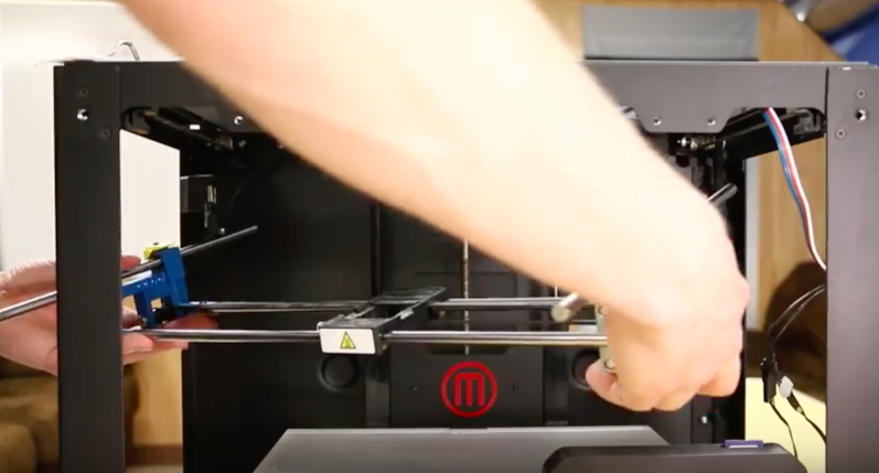
You have received your new Y-axis Aluminum Upgrade Kit for the Rep 2/2x and you’re wondering how to install it. Follow along with the video or continue reading for further instructions.
As always, turn off and unplug your machine before doing any repair work.
- Side cutters
- 5 mm Allen key
- 2.5 mm Allen key
- 2 mm Allen key
- 1/16th mm Allen key
- Cotton swab/toothpick/metal brush
- Aluminum upgrade kit
1
Removing the Extruder
- Remove the left side, front, and side panels.
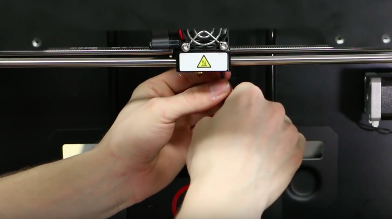
- Remove the active cooling fan ducts as well as the two bolts holding the extruder to the carriage.
- Follow the extruder cables behind the machine and cut any zip-ties that are holding the cables to the printer, (it’s possible that you don’t have any, which is fine.)
- Remove the extruder from the carriage.
- Take the cables out of the slots in the back and lay the assembly behind the machine.
2
Removing the Endstop PCB’s Cable
- Move to the right side of the gantry system where the endstop pcb and x-axis motor are located.
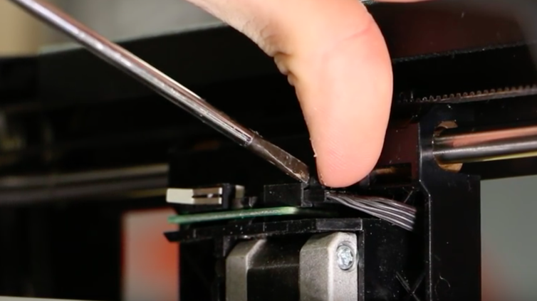
- We are going to remove the endstop pcb’s cable.
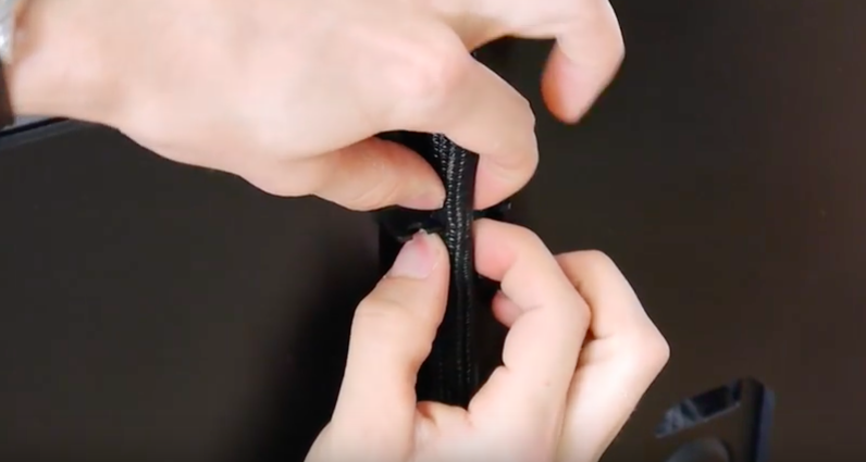
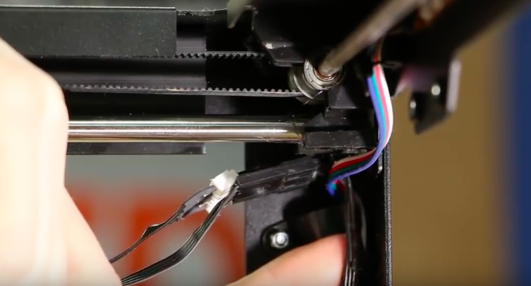
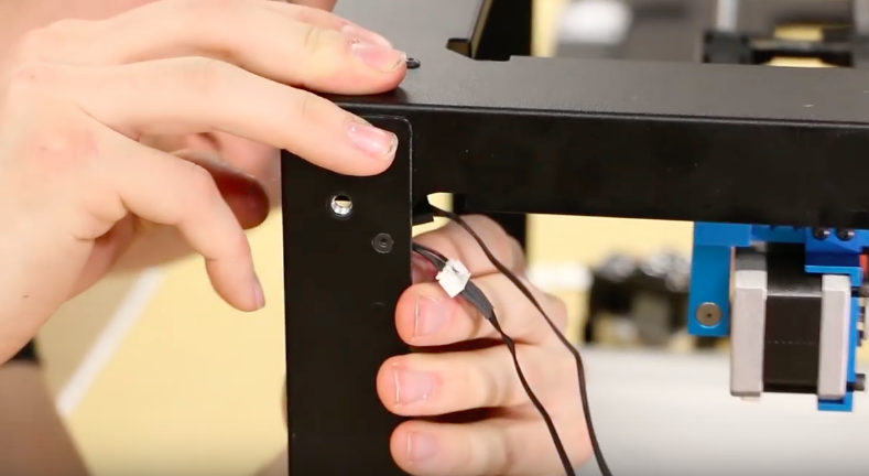
- To do this, push down on the small lever and pull. A flat screw driver may be needed.
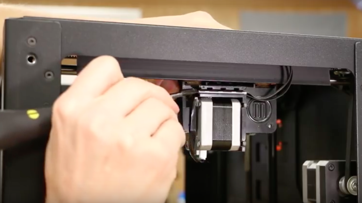
- On the outside of the same area, remove the metal pin. This will free the cables so that the endstop pcb connector can be pushed out.
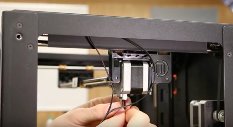
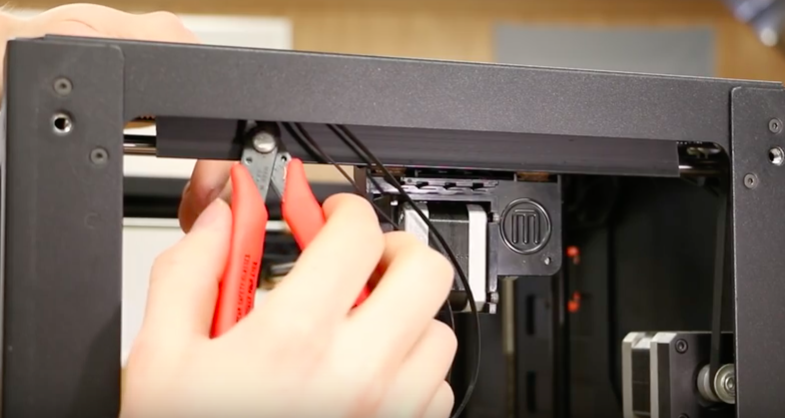
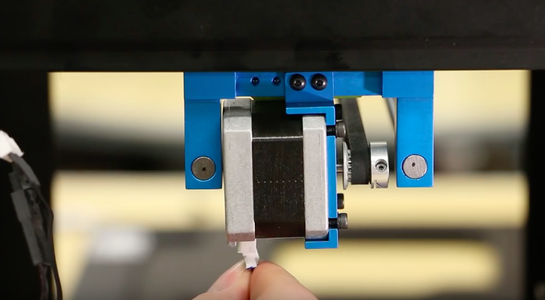
- Remove the motor cable. There should be a small zip-tie holding the cables to the top of the frame. Gently cut this to ensure no damage to the wires.
4
Removing the Gantry System
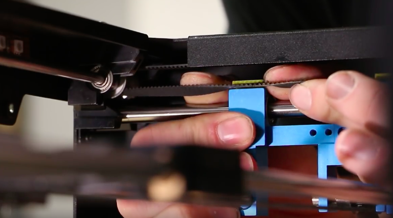
- Back on the right side of the machine, remove the belt.
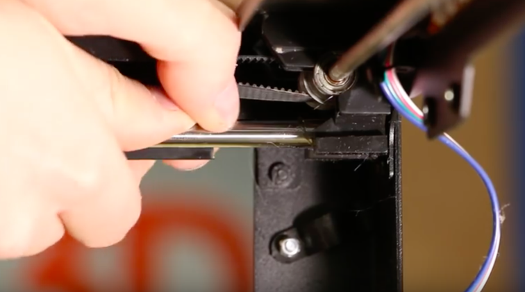
- On the same side, but in the front right corner, remove the wires from their holders.
- Loosen the small bolts or slide them out.
- Remove the wires from their first holder.
- From this angle you’ll remove the right side linear rod.
- Grasp firmly and press down. You’ll hear a loud click.
- Move to the front left corner and repeat the process.
- Push down on both the left and right linear rods to remove them from the back brackets.
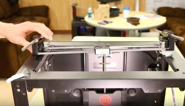
- Take the gantry system out of the printer.
6
Pulling the Y-axis off of the X-axis Linear Rods
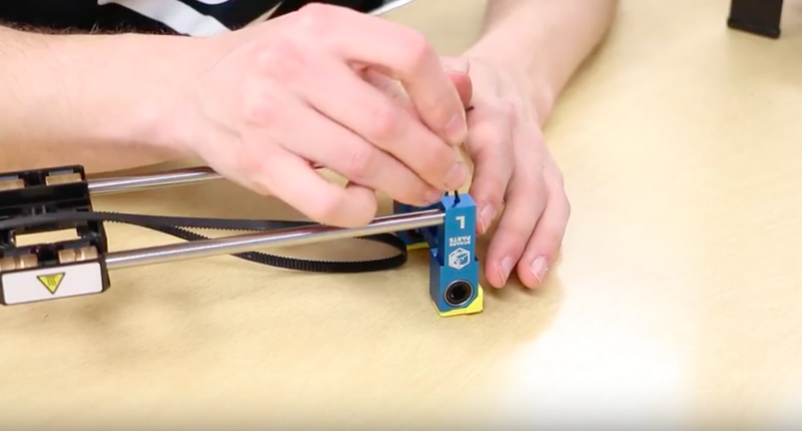
- On the left side, remove the x-axis idler pully from the y-axis secondary.
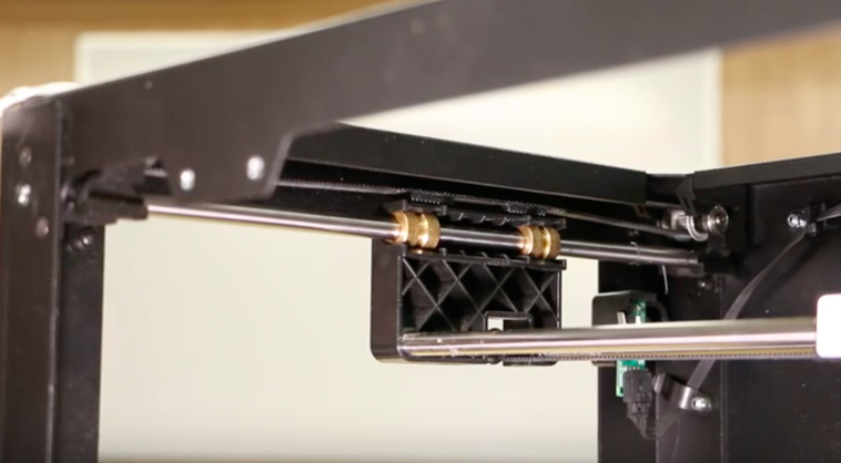
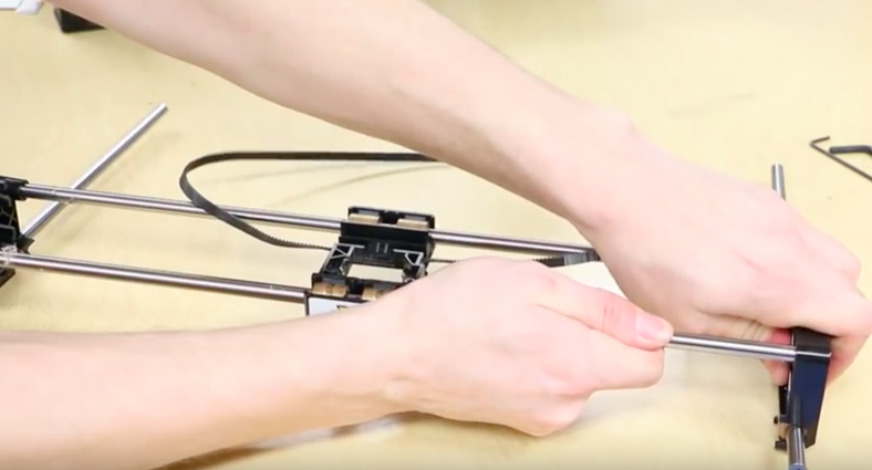
- Position the gantry system so you can pull the y-axis secondary and y-axis primary off of the x-axis linear rods.
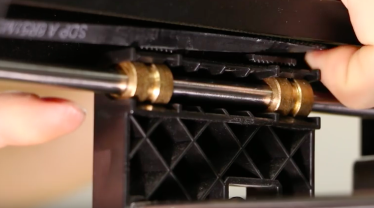
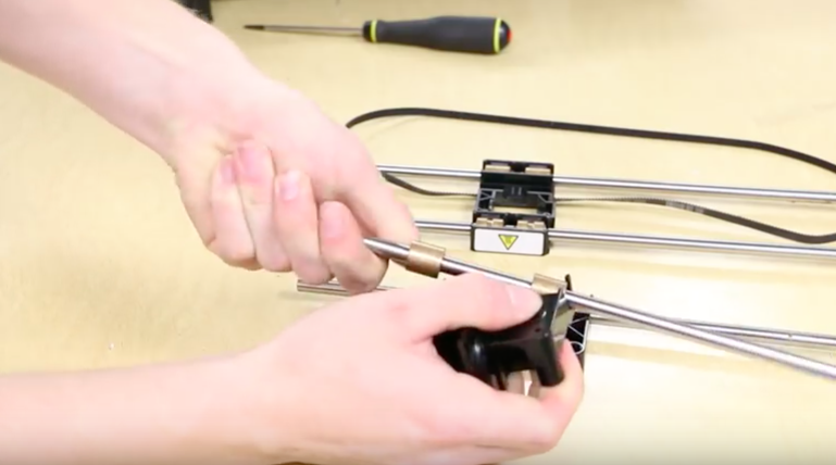
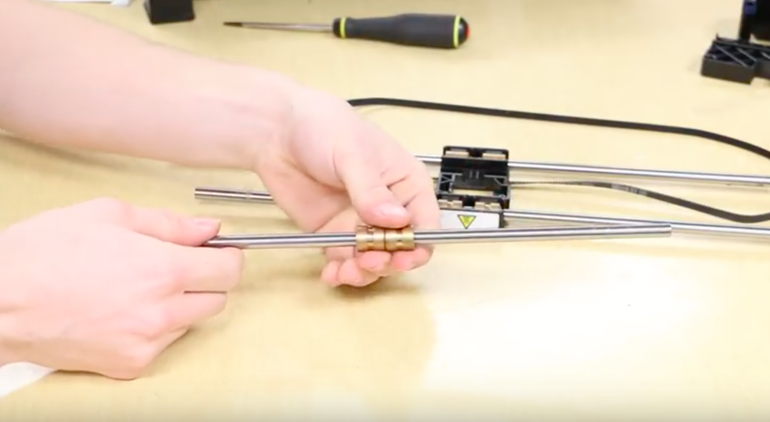
- Take the y-axis primary and y-axis secondary and remove the bushings.
- Once you have the rods out, pull the bushings of the rods when done.
7
Assembling the Motor
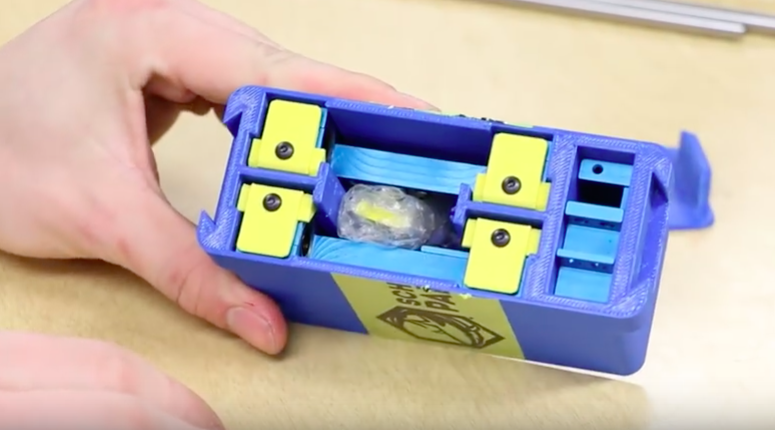
- Open the upgrade kit and remove its contents.
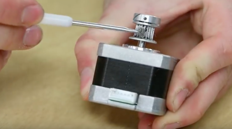
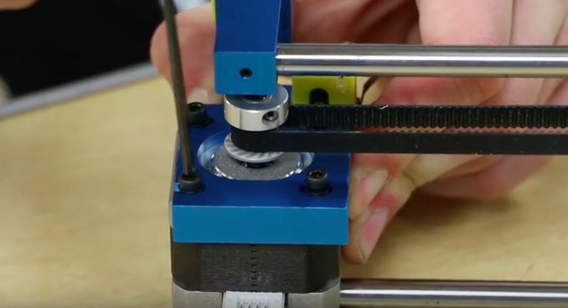
- Before proceeding, use a q-tip or a brush to clean the x-axis motor pulley, (a toothpick or knife may also be used to clear the gears.)
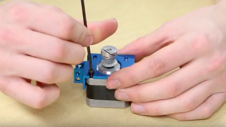
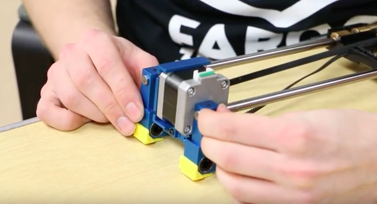
- Take the motor mount from the kit and align it on the motor.
- Flip the motor upside down, or so the motor connectors are facing down.
- Screw the motor mount onto the motor with the motor’s previous screws and washers.
- Grab the linear bracket marked “R”.
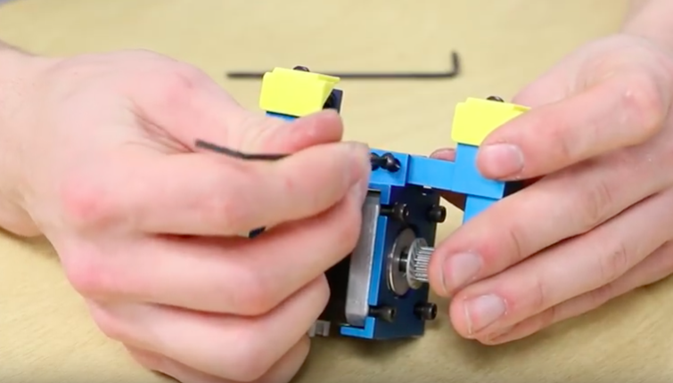
- Loosen the set screws and position the motor mount on the linear bracket.
- The motor’s pulley should be away from the “R” and screwed into the last two holes.
- Make sure that the linear bracket and motor mount are parallel to each other.
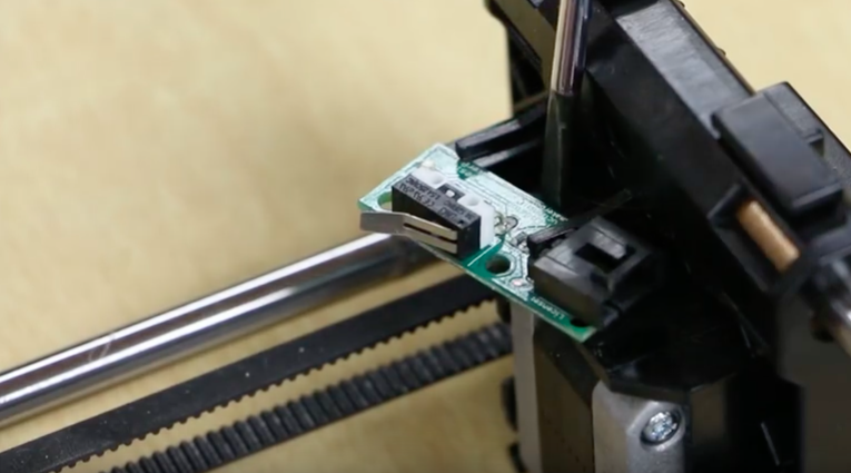
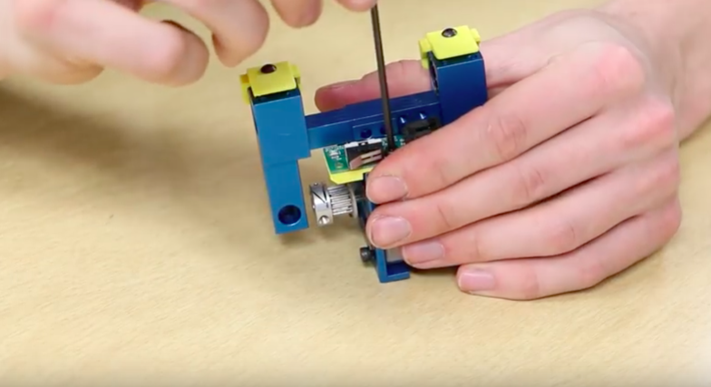
- Grab the spacer from the kit, along with the endstop pcb and its screws from earlier.
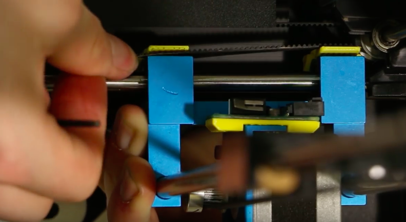
- Secure the endstop pcb onto the motor mount.
8
Reassembling the Gantry System
- Place the carriage down with the bushings facing upwards and the front of the carriage pointing away from you.
- Grab the “R” linear bracket assembly and loosen its bottom set screws.
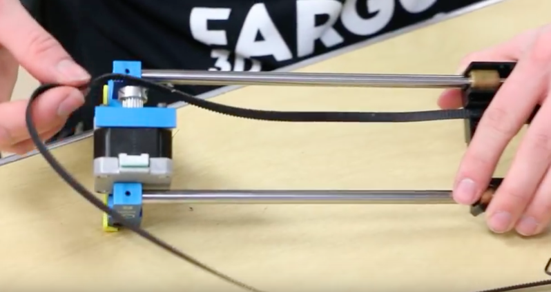
- Slide the x-axis rods into place by flushing the ends of the rod to the outside of the linear bracket.
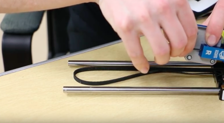
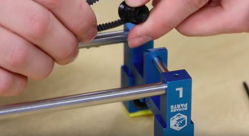
- Re-tighten the set screws and loop the belt over the motor pulley.
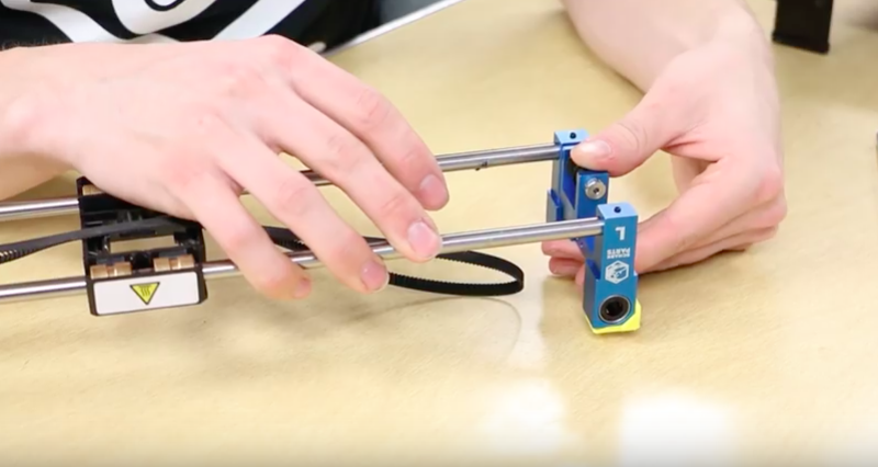
- Take the “L” linear bracket and loosen its bottom set screws.
- Slide the x-axis rods into place by flushing the ends of the rods to the outside of the linear bracket.
- Re-tighten the set screws.
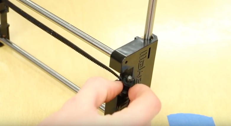
- Loosen the shoulder bolt and slide the bolt into place.
- You can add some Loctite to the shoulder bolt threads if desired.
- Re-tighten the shoulder bolt.
10
Continuing with the Gantry System
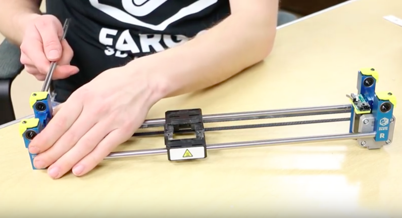
- Move the entire gantry system into the printer.
- The “L” bracket on the left side and the “R” bracket on the right side.
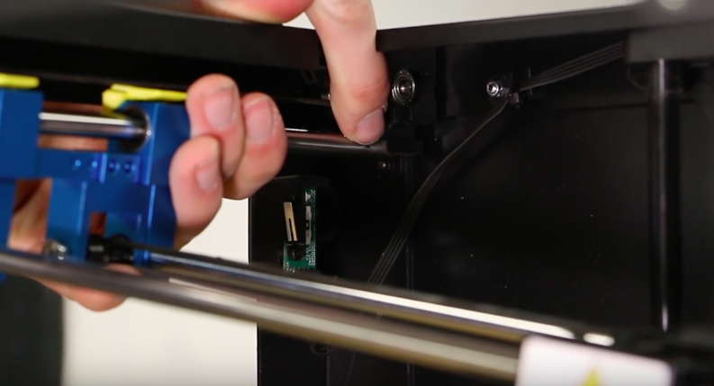
- In the back left corner, press the linear rod into place; you’ll hear a loud click.
- Do the same for the front left, rear right, and front right.
- Make sure that no cables get caught between the rod and the bracket.
- The gantry system should move freely in all directions.
11
Reinstalling the Belts
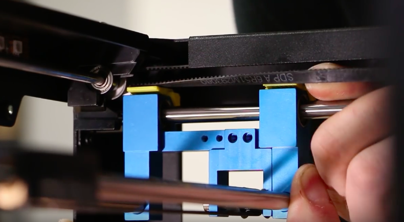
- On the left side, move the linear bracket as far forward as possible.
- Hold the forward pressure while you loop the belt underneath the back belt clamp.
- Move to the right side of the printer and push the linear bracket as far forward as possible.
- Hold the forward pressure while you loop the belt underneath the back belt clamp.
- You can now move the carriage away from the front and loop the belts underneath both of the front belt clamps.
12
Finishing Up
- Replace the front right wires into their holders, (if you loosen the nuts, re-tighten them.)
- Reconnect the pcb endstop cable and motor cable. Replace the zip-tie to the frame.
- Re-set the extruder cables on the back side of the machine and secure the extruder to the carriage.
- Replace the side covers to complete the installation.


